Flex and Rigid-Flex Printed Circuit Design
Author: Shenzhen capel technology co., LTDissuing time:2017-09-13 10:34:16Pageviews:5361【smallinBig】
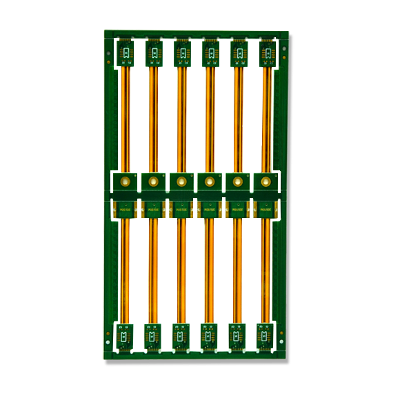
A rigid-flex circuit, designed to tightly integrate into its enclosure.
WHAT IS RIGID-FLEX?
As the name suggests, a flexible printed circuit is a pattern of conductors printed onto a flexible in...
Text labels:
A rigid-flex circuit, designed to tightly integrate into its enclosure.
WHAT IS RIGID-FLEX?
 As the name suggests, a flexible printed circuit is a pattern of conductors printed onto a flexible insulating film. Rigid-flex is the name given to a printed circuit that is a combination of both flexible circuit(s) and rigid circuit(s), as shown in the image above. This combination is ideal for exploiting the benefits of both flexible and rigid circuits - the rigid circuits can carry all or the bulk of the components, with the flexible sections acting as interconnections between the rigid sections.Flexible circuit technology was initially developed for the space program to save space and weight. They are popular today as they not only save space and weight - making them ideal for portable devices such as mobile phones and tablets - they can also: reduce packaging complexity by substantially reducing the need for interconnect wiring; improve product reliability due to reduced interconnection hardware and improved assembly yields; and reduce cost, when considered as part of the overall product manufacture and assembly costs.Flexible circuits are normally divided into 2 usage classes: static flexible circuits, and dynamic flexible circuits. Static flexible circuits (also referred to as use A) are those that undergo minimal flexing, typically during assembly and service. Dynamic flexible circuits (also referred to as use B) are those that are designed for frequent flexing; such as a disk drive head, a printer head, or as part of the hinge in a laptop screen. This distinction is important as it affects both the material selection and the construction methodology. There is a number of layer stack-up configurations that can be fabricated as rigid-flex, each with their own electrical, physical and cost advantages.RIGID-FLEX DESIGNDesigning a flex or rigid-flex circuit is very much an electromechanical process. Designing any PCB is a 3 dimensional design process, but for a flex or rigid-flex design the 3 dimensional requirements are much more important. Why, because the rigid-flex board may attach to multiple surfaces within the product enclosure, and this attachment will probably happen as part of the product assembly process. To ensure that all sections of the finished board fit in their folded location within the enclosure, it is strongly recommended that a mechanical mock up (also known as a paper doll cut out) is created. This process must be as accurate and realistic as possible with all possible mechanical and hardware elements included, and both the assembly-time phase and the finished assembly must be carefully analyzed.
For a engaging discussion on the materials, technologies and processes used in rigid-flex design, as well as information about the challenges involved with the production of a rigid-flex board, check out Ben Jordan's blog on Rigid-Flex - Part 1, Part 2, Part 3, Part 4, Part 5.MATERIALS USED IN FLEXIBLE CIRCUIT MANUFACTUREFlex circuits are created from a stackup of flexible substrate material and copper, laminated together with adhesive, heat and pressure.The most common substrate is polyimide, a strong, yet flexible thermosetting polymer (thermoset). Examples of polyimides often used in the manufacture of flexible circuits include: Apical, Kapton, UPILEX, VTEC PI, Norton TH and Kaptrex. Note that these are registered trade names, owned by their respective trademark holders.
The copper layer is typically rolled and annealed (RA) copper, or sometimes wrought copper. These forms of copper are produced as a foil and offer excellent flexibility. They have an elongated grain, it is important to orient this correctly in a dynamic flex circuit to achieve the maximum flexing lifespan. This is achieved by orienting the dynamic flex circuit along the roll (so the circuit bends in the same way the foil was coiled on the roll). The flex manufacturer normally deals with this during the preparation of fabrication panels, it only becomes an issue if the designer performs their own circuit panelization (referred to as nesting in flex circuit design). The copper foil is typically coated with a photo-sensitive layer, which is then exposed and etched to give the desired pattern of conductors and termination pads.The adhesive is typically acrylic, and as the softest material in the structure, introduces the greatest number of manufacturing challenges. These include: squeeze-out, where the adhesive is squeezed out into openings cut into the cover layers to access copper layers; Z-axis expansion defects due to the higher CTE (coefficient of thermal expansion) of acrylic adhesive; and moisture out gassing due to the higher rate of moisture absorbance, which can result in resin recession, blow outs and delamination at plated through hole sites. Alternative adhesives and adhesive-less processes are available, these may be more appropriate in less cost-sensitive applications.
 A simplified view of how a flexible circuit is manufactured, the materials are laminated together under heat and pressure.
FLEX LAYER STACKUP TYPES
A simplified view of how a flexible circuit is manufactured, the materials are laminated together under heat and pressure.
FLEX LAYER STACKUP TYPES
There are a number of standard stackups available for flex and rigid-flex circuits, referred to as Types. These are summarized below.
2017-09-13
5361People browsing
Back